Levitation Clock
I’ve been meaning to post this for awhile, but better late than never I guess. For my senior design project in college, myself and two buddies of mine, Trong and Holden, (all of us nearly done with our Master’s degrees at the time) decided to build a clock… but no ordinary clock, no. We wanted to build a clock that used magnetic levitation to tell time. Our final implementation was VASTLY different from our original, but we were incredibly happy with how it turned out:
Design
Each object is a “bit” and tells time in a binary way (sort of). You can tell what hour it is by counting the number of lines on the cylinders currently levitating (or realize that if the first and third objects are levitating that it corresponds to a binary 1010 which means it’s 10 o’clock!). I’ll talk about the design process in the next few sections (and include our eagle files and arduino sketches), but you can find some more information in the Final Paper and Presentation I’ve linked. User Interface This was a very simple block: it just had three buttons and four seven-segment displays so that the user could set the time on the clock. The main control board handled all the timing and it was sent via a custom data cable to this daughter board. Files: Eagle Schematic Eagle PCB Layout PCBA Drawing BOM Power Cable Drawing Data Cable Drawing
Main Controller
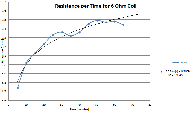
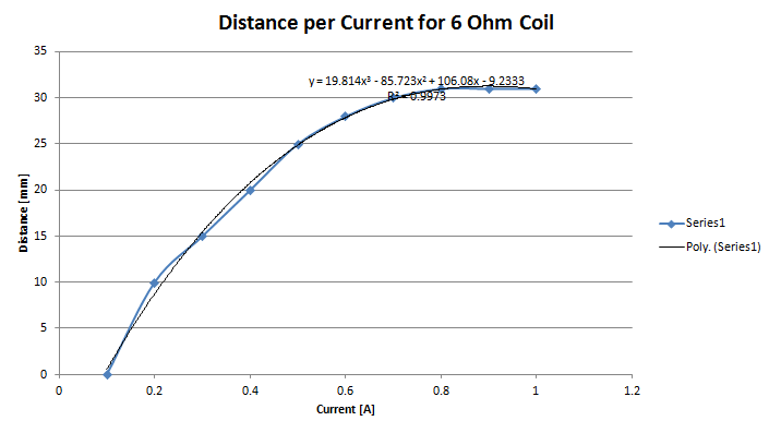
This block was the brains of the operation. For simplicity, we opted to use an arduino for prototyping and then we just inserted the pre-programmed chip into a 28-pin socket on the board. We could have added in programming pins but decided to save the effort since there wouldn’t be much need to program more than once. The bulk of this board consisted of the MOSFETs used to drive the solenoids (each of which could draw around 750mA of current when on), the microcontoller, Buck Regulator, and RGB LED used to tell minutes. The primary concern was that of driving the solenoids. Given that one solenoid could be on for four hours at a time and that all four would be encased in, essentially, a wooden oven, we needed to run some temperature tests and also make sure that our drivers could properly dissipate the required amount of heat. First, we ran a test to see what resistance our solenoid would saturate at as a function of time (positive temperature coefficient so more time equals more heat which equals more resistance which implies less levitation height). We also ran a test to see what amount of levitation height we could coax out of it as a function of current. Based on the following plots, we settled on a ~6 Ohm coil with 750 mA current draw. As the video at the beginning of this post shows, this gave us enough levitation height for it to be discernible from a non-levitating object and allowed us to minimize power consumption to some degree.
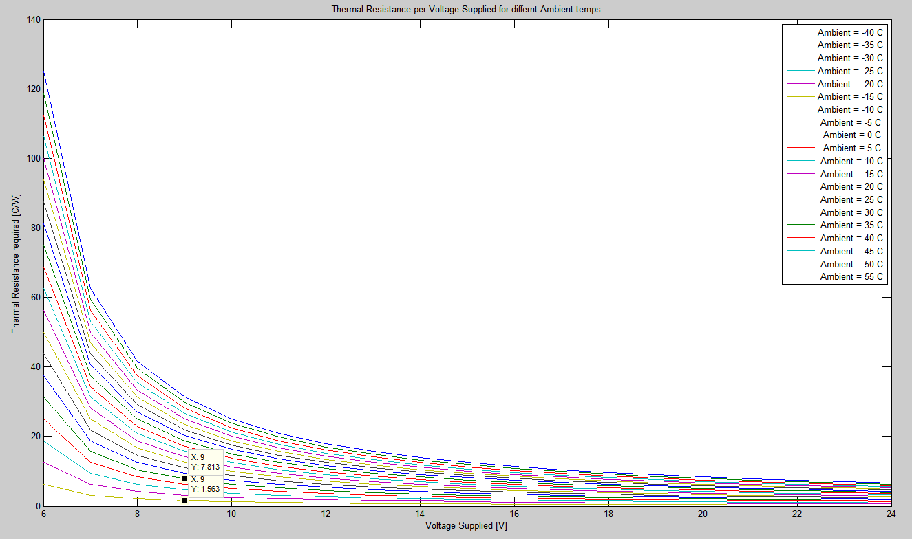
Next, I ran a script in MATLAB in order to determine the required heatsink thermal resistance at varying ambient temps and voltage levels. For our design, we needed a roughly $ 2\frac{^{\circ}C}{W} $ heatsink.
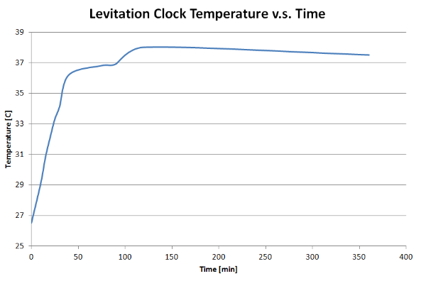
While we’re on the subject of temperature, we also ran a test while we were presenting at Imagine RIT in order to gauge what our ambient temperatures looked like as a function of time. Now, this is kind of a useless test since we were running in “demo” mode (as shown in the video above) where we speed up time by 60x so that one “minute” passes by as one second. However, it does give us some very valuable information in that we would NEVER want this running in normal operation without some kind of fan circulating air internally. We saw roughly a 10C rise when one coil would only be on for a maximum of four minutes… just imagine four hours. Yikes. Holden and I ended up testing it over a 24-hour period in “normal” with a little 60mm computer fan blowing air through the gap at the bottom of the frame and we never saw the ambient increase above 50C so we should have done a MUCH better job analyzing internal heat generation compensation.
Files:
- Eagle Schematic
- Eagle PCB Layout
- Arduino Sketch
- PCBA Drawing
- BOM
- Power Cable Drawing
- Solenoid Drawing
- Solenoid Cable Drawing
- Levitating Object Drawing
Frame Design
Our frame was designed by an awesome Industrial Designer we brought into the project named James. A week after bringing him on, he bombarded us with LOADS OF CONCEPTS. This made us really think about implementation more which is how we converged on the “binary” version of this clock. James ended up designing a beautiful frame that we ended up paying a friend of Holden’s named Byron Conn to make (he’s an awesome wood-worker). We basically just wanted a really beautiful and aesthetically pleasing frame in order to tie the whole project together, and BOY did James and Byron deliver!

Files:
Final Thoughts
Overall the project was rather simple from an electronics standpoint, but the design process from product definition up through the final stages was a very interesting experience. There are many, many, things I think all of us would do differently if we were to tackle this project again but it was very useful to make some of the mistakes we did (the biggest one being that we ignored how to properly handle the ambient heat from the solenoids). Anyways, at the end of the day I’m still really proud of this thing even if it’s ultimately useless. It’s just… cool which is all we ever wanted from this project to begin with.
- Share this post!


Tags:
university project