Optimization Algorithms for Circuit Design
Over this past summer as I was wrapping up my Master’s thesis, I was taking a class involving the study of AI algorithms. Due to my thesis work involved switched DC-DC converters, I had the idea of implementing a Genetic Algorithm in order to design a Boost Converter (this was a graduate class so it was very research-based and each student had to come up with a project to pursue and then present at the end of the class). I ended up scaling back my original idea due to time constraints (10-week schedule plus I needed to revise my thesis and prepare for my defense) so I decided to focus on implementing both a Genetic Algorithm (GA) and Particle Swarm Optimization (PSO) in order to design an optimal controller for a Boost Converter. The paper (which can be found here) I wrote will go into the implementation details much more thoroughly, but I’ll give an overview in this post. I also have my MATLAB code up on my github page if anyone wants to play around with it.
The Problem
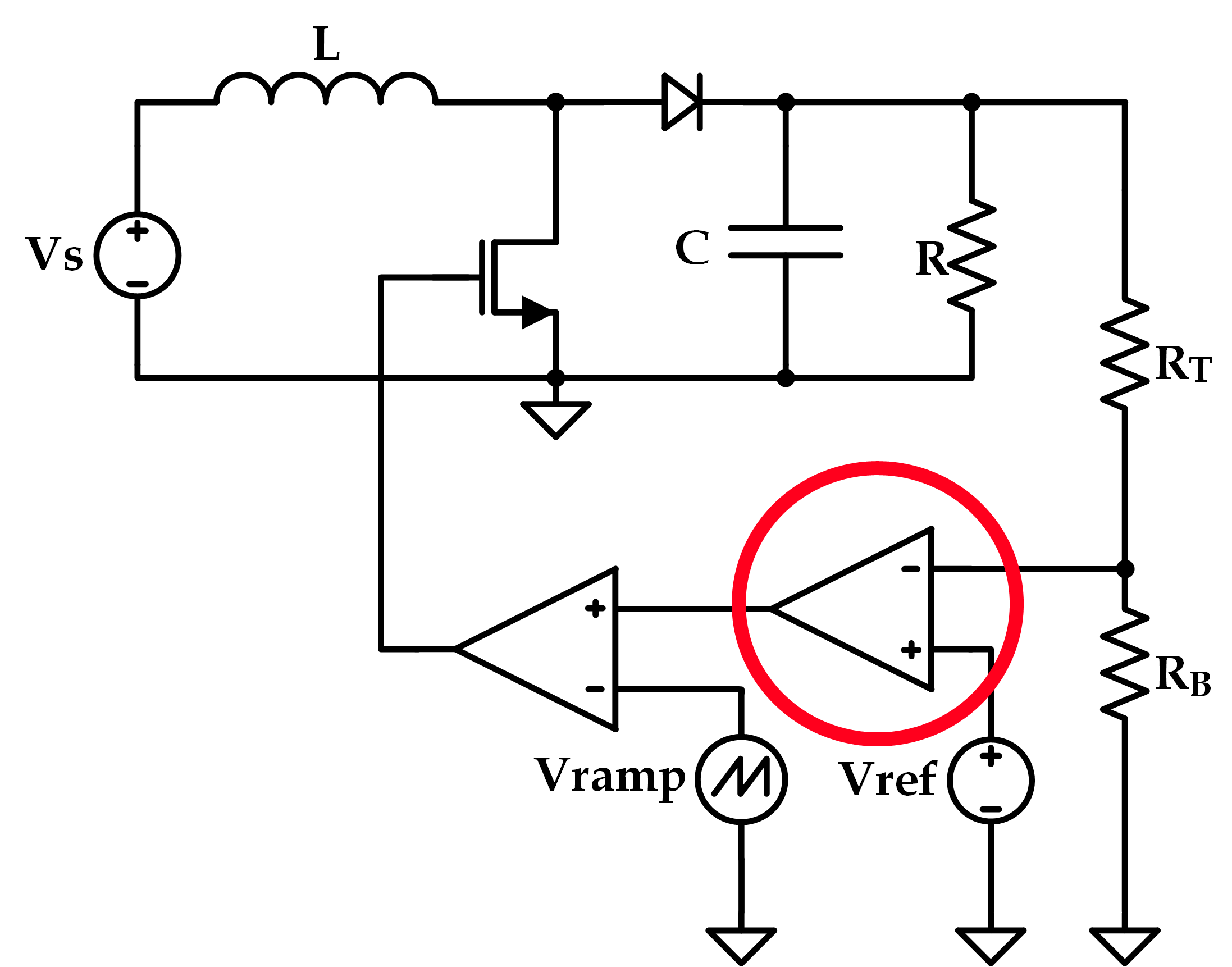
Depending on the architecture of a given Boost Converter (or any switched-converter for that matter) is that the design of the controller that is in the feedback loop has to be approached very carefully [this is the part circled in red in the schematic below]. The reason is rather obvious: feedback = potential for instability - thus it’s important to design a compensation network that provides a good balance between speed (bandwidth) and stability (phase-margin) but that can also maintain a very precise output voltage (gain). There are many possibilities, but the classical approaches are to use a Lag, Lead, or PID controller which all have well-understood equations pertaining to pole and zero placement (again, for more information you can read my paper on this project or read one of the MANY papers I referenced).
The Plan
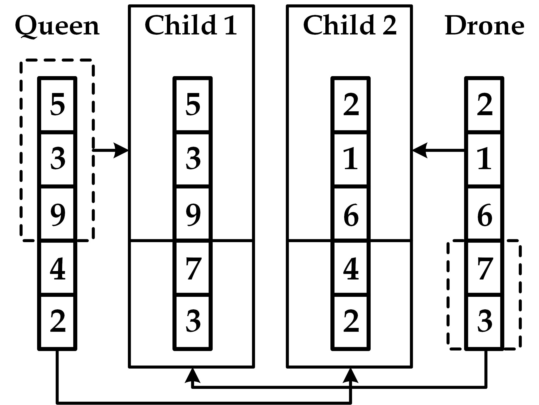
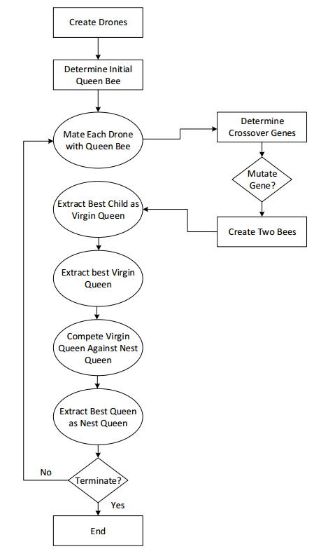
Step one was to understand how I wanted to implement my algorithm. I primarily focused on Genetic Algorithms at first as I personally felt it would involve more thought than PSO (and I was right, to an extent). A big issue with GAs that I discovered throughout my research is that most of the algorithms absolutely LOVE to converge on a locally optimal solution, rather than the globally optimal one. Luckily, this wasn’t as big of an issue for my project since I had no intention of making an algorithm that will find the BEST solution for a circuit design problem: I’m not even sure we’ll ever get to that point. Far too many variables. What I wanted was for my program to spit out a circuit that a designer could start with rather than spending a lot of man-hours trying to converge onto the same starting point. Anyways… I ended up implementing a variant of GA with elitism that bases itself off of a bee colony- I ended up calling it QBGA (Queen Bee Genetic Algorithm). Essentially you have a queen bee and a multitude of “drone” bees that have randomly generated “genes”. Every generation, each drone mates with the queen and produces two virgin queen bees with a sample of genes from both parents (explained graphically below). The drone is then killed. The two new “virgin queens” then compete and the best one survives. Once this process is completed for each drone, the new virgin queens then enter another tournament round until only one remains. This virgin then attempts to usurp the current queen bee’s throne and either succeeds, becoming the new queen, or fails and simply dies off. This method, below in graphical form, allows for a very large solution space to be explored (because of all the random behavior) but still maintains a connection to the best solution found so far via the queen bee.
A bee’s genes consisted of transfer function coefficients which could then be used to calculate the phase margin, gain, etc (which, unsurprisingly, I used as my fitness function). The Implementation I quickly discovered that my original plan had a few problems with convergence. In order to alleviate this, I implemented a parabolic fitness function with penalties applied if a solution exceeds some predefined bounds whose equation is shown below where $ \alpha_i $ is a coefficient for a fitness variable $ \theta_i $
++F = \sum_{i=1}^N -\alpha_i(N(\theta_i) - 1)^2 + \alpha_i - P(\theta_i) ++
$ N(\theta_i) $ is a normalization function and $ P(\theta_i) $ is a penalty function. I also implemented age behavior for the queen bee. Essentially, as the queen maintains her position as queen of the hive, the gene mutation rate begins to increase in order to try and prevent convergence on a local optima. If, however, the queen is already the global-best solution, the extra mutation will have no impact on the solution so it could ONLY help. As it turns out, it doubled the accuracy of the algorithm (more details in my paper). Below is the comparison between this QBGA implementation and three different forms of PSO (none of which I’ve covered in this post). The three PSO algorithms are a constriction PSO, Chaotic Decreasing Intertial Weight (CDIW) and Chaotic Random Intertial Weight (CRIW). More information can be found in my paper (surprise!).

Links:
- Share this post!


