Opamp Noise Analysis
Continuing with the theme from my last post, I have some more neat noise analysis; this time looking at an Opamp. Most people would probably end up using this type of analysis rather than looking at a circuit transistor-by-transistor. Here you can grab the datasheet for you opamp and calculate the output noise you’d end up seeing. Here I’m going to look at Analog Device’s OP27. Before we move on, we’ll need to extract some very important parameters from the datasheet: Input Noise Voltage, Input Noise Current, Gain Bandwidth Product, and Common Mode Input Resistance. (Note that the worst-case values were used where multiple values were presented. All values from the OP27A/E column.):
++ e_{n} = 5.5 \frac{nV}{\sqrt{Hz}} \ i_{n} = 4.0 \frac{pA}{\sqrt{Hz}} \ GBW = 8.0 MHz \ R_{in,cm} = 3 G\Omega \ ++
The first thing we need to do before analyzing the amp is to convert $ e_{n}$ and $ i_{n}$ into $ e_{n}^{2}$ and $ i_{n}^2$. To do so, simply square the quantity and multiply by the GBW. This yields the following values:
++ e_{n}^{2} = 2.42\times 10^{-10} V^{2} \ i_{n}^{2} = 1.28\times 10^{-16} A^{2} \ ++
Now we can create a noise model for the opamp. We will have voltage noises due to the resistors, an input-referred voltage noise source on one pin (calculated above) and TWO input-referred current noise sources (again, calculated above). Note that R2 is placed specifically to lower noise, and we’ll analyze the effects of taking it out to show why it’s necessary. The resistor values were chosen to exacerbate the noise problem.
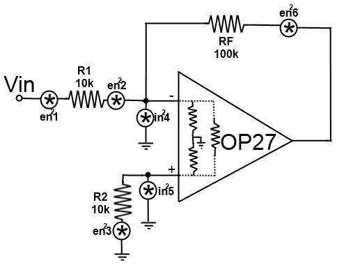
Our process will be the same as in the BJT case where we will analyze the contributions of each source at the output and then find the total input-referred noise from all sources.
1) Thermal Noise from R1
$ e_{n1}^{2} = 4kTR\delta f = (1.66\times 10^{-20})(10\times 10^{3})(8\times 10^{6}) = 1.328 \times 10^{-9} V^{2}$ Since it is an inverting amplifier and we are on the ‘-‘ pin of the amp, gain is just $ A = \frac{RF}{R1} = 10 \frac{V}{V}$. Therefore, $ e_{n1,o}^{2} = (1.328 \times 10^{-9})(10)^{2} = 1.328 \times 10^{-7}$
2) Input Referred Voltage Noise
This will simply be the value we already calculated times the square of the gain, or $ e_{n2,o}^{2} = (2.42\times 10^{-10})(100) = 2.42\times 10^{-8} V^{2}$. You should be able to see why this is a low-power amp. Clearly, the thermal noise of the resistance is going to be a larger factor since it is an order of magnitude larger than the noise inherent to the internals of the opamp itself.
3) Thermal Noise from R2
$ e_{n3}^{2} = 4kTR\delta f = (1.66\times 10^{-20})(10\times 10^{3})(8\times 10^{6}) = 1.328 \times 10^{-9} V^{2}$. Since we are on the non-inverting side, we need to calculated the non-inverting gain which is just $ A = 1+\frac{RF}{R1} = 11$ so $ e_{n3,o}^{2} = (1.328\times 10^{-9})(11)^{2} = 1.607 \times 10^{-7} V^{2}$
4) Input Referred Current Noise (‘minus’ pin)
First, we need to convert our already calculated current noise value into a voltage. This requires us to look at the equivalent resistance that this source sees. It should be obvious that we’ll see R1 in parallel with the input common-mode resistance; since $ R_{in,cm} » R1$, we can approximate the equivalent resistance as $ 10k\Omega$. Thus, $ e_{n4}^{2} = (1.28\times 10^{-16})(10\times 10^{3})^{2} = 1.28 \times 10^{-8}$. It follows that $ e_{n4,o}^{2} = (1.28 \times 10^{-8})(10)^{2} = 1.28 \times 10^{-6} V^{2}$
5) Input Referred Current Noise (‘plus’ pin)
Obviously, the calculation here will be the same as the previous with the only modification being the gain (11 as opposed to 10). Thus, $ e_{n5,o}^{2} = (1.28 \times 10^{-8})(11)^{2} = 1.549 \times 10^{-6} V^{2}$
6) Thermal Noise from RF
$ e_{n6,o}^{2} = e_{n6}^{2} = 4kTR\delta f = (1.66\times 10^{-20})(100\times 10^{3})(8\times 10^{6}) = 1.328 \times 10^{-8} V^{2}$
Total Noise
Summing all of these values up yields and output noise of $ e_{no,total}^{2} = 3.16\times 10^{-6} V^{2}$ which, when dividing by the square of the gain yields an input noise of $ e_{ni,total}^{2} = 3.16 \times 10^{-8} V^{2}$. Converting this to more friendly units yields our final answer of: $ e_{ni, total} = 62.85 \frac{nV}{\sqrt{Hz}}$. This means that just by adding resistors the opamp’s noise increased by a staggering 1043% (not totally true. We’re also taking into account the input current noise which is a HUGE fraction of the noise figure)!
So what’s with R2?
If we’re increasing the noise by about 1000% just by adding resistance, shouldn’t we remove R2? The opamp will function fine without it so why include it at all? I’ll tell you why. Take a look at $ i_{n5}^{2}$ again. What resistance does it see when R2 is removed? That’s right: $ R_{in,cm}$ which, for this opamp, is $ 3 G\Omega$. Calculating the new input noise yields a value of $ 1.32 \frac{mV}{\sqrt{Hz}} = 1.32\times 10^{6} \frac{nV}{\sqrt{Hz}}$. That’s roughly 1 million times bigger than the intrinsic noise in the opamp! An absolutely massive increase for such a little circuit change. Moral of the story: keep R2 in the circuit.
What happens if we reduce the resistance values?
That’s a good question. Say we reduce all resistors by a factor of ten such that $ R1 = R2 = 1k\Omega$ and $ RF = 10k\Omega$. Recalculating all of the noise values results in $ e_{ni,total} = 10.2 \frac{nV}{\sqrt{Hz}}$ which is an 83.8% decrease from the previous value (and only an 85.5% increase from the opamp’s intrinsic noise). By reducing the resistance by a factor of 10, we can reduce the noise substantially (from 1000% variation to just under 90% variation). Second moral of the story: don’t use large resistances (unless absolutely necessary and the noise can be tolerated)!