Circuit Design Interview Questions: Part II
Building off of my previous post Circuit Design Interview Questions: Part I, we’ll now explore some slightly more advanced questions (still, they should be solvable by any EE graduate with some basic analog circuit knowledge).
Question 5
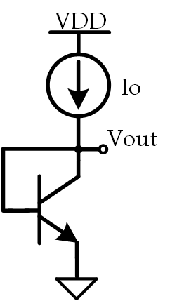
If a constant, temperature invariant, current $ I_O $ is fed into the collector of a BJT, as shown below, what happens to $ V_O $ as the temperature is increased?
Solution
This question is good as it tests basic BJT temperature dependance understanding which, from an analog circuit design perspective, is very important as it is the basis of bandgap voltage reference design. As long as you know that $ \frac{\partial V_{BE}}{\partial T} \approx -2 \frac{mV}{^{\circ}C} $, you’ll know that $ V_O$ will decrease as temperature is increased.
Question 6
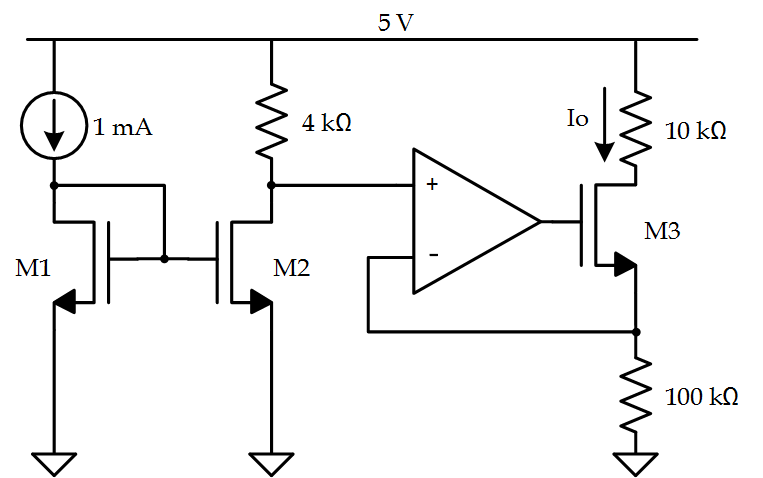
Given the circuit below, what is $ I_O$?

Solution
The answer is clearly $ 1\,mA $ since it’s just a basic current mirror. However, if you’re interviewing a co-op, they may have never been exposed to current mirrors or maybe they’re a bit rusty.
Question 7
Given the circuit below, find $ I_O $:
Solution
This question is nice as it combines basic Op Amp and basic current mirror understanding. Since the input to the Op Amp is generated by a current mirror, we know that the current through $ R_{4k\Omega} $ is equivalent to $ 1\,mA$. Hence, $ \frac{5\,V - V_+}{4\,k\Omega} = 1\,mA$ which means that $ V_+ = 1\,V$. Since the inverting and non-inverting terminals of the amplifier will be equal, the voltage at the source of M3 will equal $ 1\,V $ which means the current, $ I_O$, can be found by diving this voltage by the resistance at the source of M3. This yields the answer that $ I_O = 10\,\mu A$
Question 8
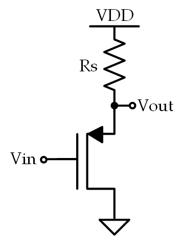
What is the voltage gain of the following circuit?
Solution
This particular amplifier is a common-drain (or source-follower). Typically, the voltage gain is simply approximated to be equal to 1, but that’s not what we’re looking for here. We want the expression for the voltage gain- granted, with some reasonable assumptions, the expression IS approximately equal to 1 but let’s get the expression first, shall we? First, let’s draw the small-signal model:
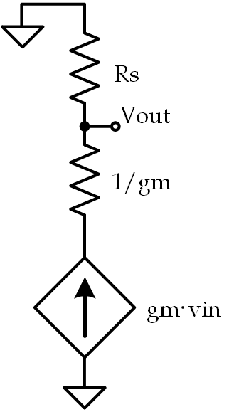
Here we have a resistance, $ R_S$, in parallel with a dependent current source with a series resistance, $ \frac{1}{g_m} $. This means that the expression for the output voltage should be: $ v_o = g_m(v_{in} - v_o)R_S $ Thus, the expression for the small-signal voltage gain is: $ \frac{v_o}{v_{in}} = \frac{g_mR_S}{1+g_mR_S} $